Insert one of the 2040 aluminum rails inside the other to create the MAST. The two lateral rail connectors will make it solid and a unique part. Tighten up the bolts completely.

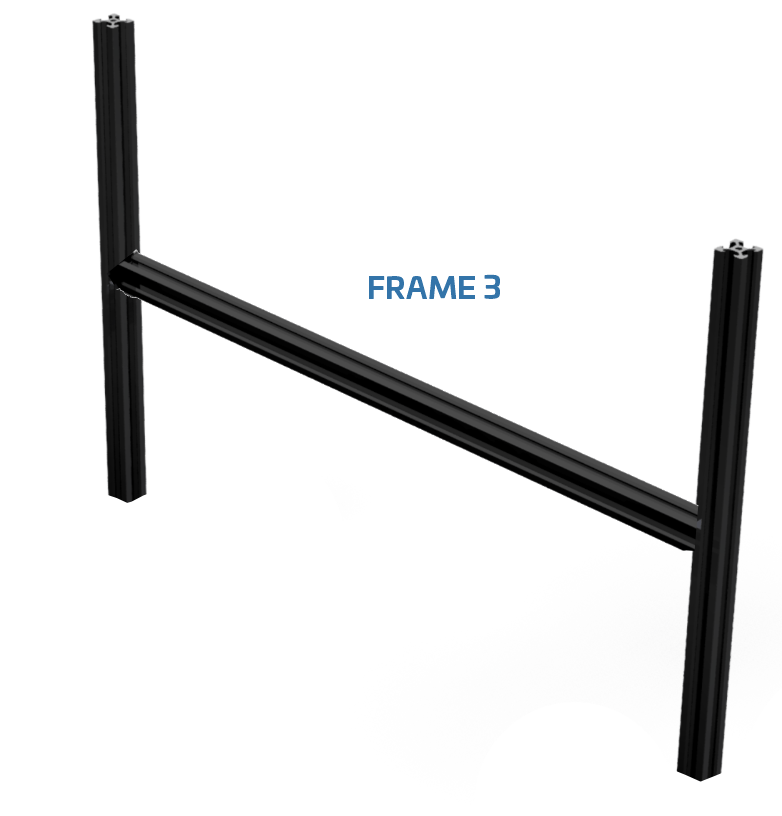
Insert the frame 3 as shown below. Push it to the very end and tighten the headless bolts while pushing.

Now, insert the MAST between the two triangular metal angle supports but keeping both nuts oriented, so you can slide, easily, the mast into its place. Do not completely tight the two side bolts, you need to leave them loose for now. Place the mast centred. There is a sticker marking the middle of the aluminium rail for your convenience.
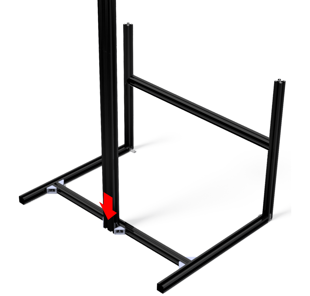
Do not completely tight the two side bolts, you need to leave them loose for now.
Place the 4 white diffusers as indicated below. With the KIT you got 6 light diffuser: 1x 50×30 cms (to be placed at the back of the inspection box) + 2x 40×40 cms (laterals) + 1x Frontal. The two remaining diffusers will be placed on the upper side of the chamber.


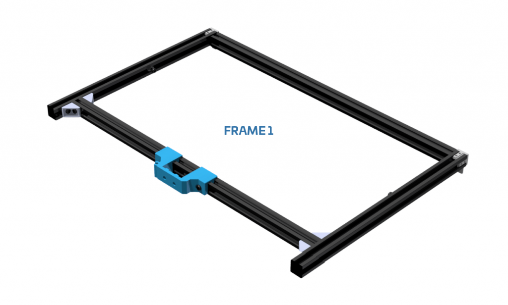
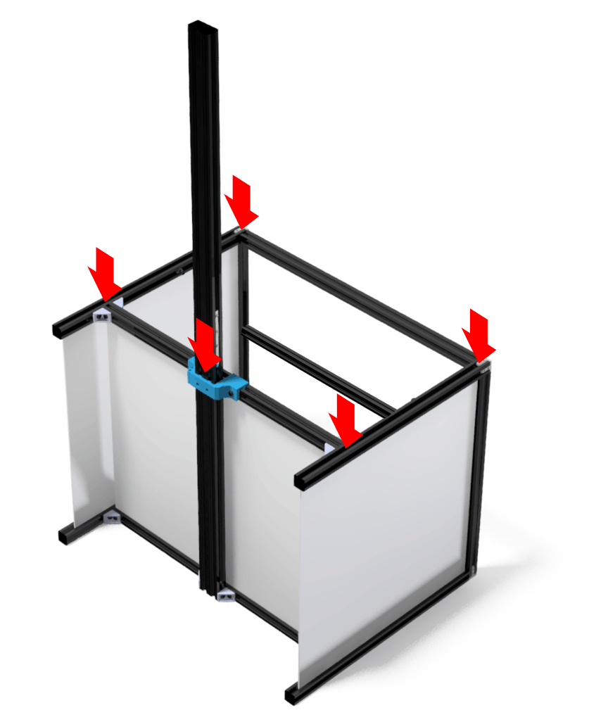
Insert the FRAME 1 sliding it using the mast as guide. The diffusers and frontal aluminum rails, will let you know the correct level for this FRAME 1. Once set, tighten the bolts you will find in the back plastic part and the base bolts you left loose in the STEP 3. Everything should get solid at this point. Detailed image below.
The lateral LED panels have to be attached to the upper rails using the bolts already located in the plastic parts. Use the silver bolts to attach the LED panels to the plastic parts. You can pass the power cables through the gap you can find between the back and lateral diffuser panels.

You can fix the action button provided to the base of the right/left aluminum vertical rails using a bolt and NUT as in the image below. 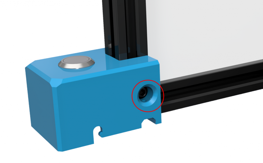 Now place the two upper diffusers (2) on the upper side as indicated. They will reflect the light emitted by the LED Panels.
Bend the diffusers a bit in order to place them inside the channels.

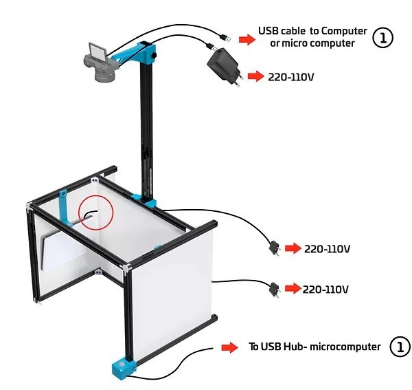
Attach the camera to the ARM plastic part using a camera screw. Then, insert the ARM into the MAST and fix it using the lateral bolt. Done.
The last step would be placing the ESD mat under the structure and connect the ground lead to any GROUND you have near the inspection platform.